
Relay Logic Configuration
GRIDlink Series 113 & 135 with Control Logic ver. 6000.22 (released June 20, 2021)
The control logic for relay output is written to registers tagged logic_relay1-8 (See Modbus Registers Table below) and are transferred to onboard I/O when USER_TRANSF_IO is TRUE. See Notes 1-4.
Relay 1 (PENDING) Configuration
Relay 1 (PENDING) is configured by default ( pendConfig = 0 ) to follow the PENDING signal from it’s onset and remain ON throughout the Event. When pendConfig = 1, Relay 1 will be ON prior to the Event by the time set in ramp_start1 and OFF during the Event. The is useful for Pre-Cooling HVAC or alarm beacons. ramp_end1 is not used.
Relay 2 (MODERATE) / Relay 3 (HIGH) Configuration
Single Relay Output
Relays 2 and 3 are configurable to act independently when SINGLE_RELAY_OUT = TRUE. This is useful if a load is dedicated to a MODERATE Event and another to a HIGH Event and it is desired not the shed both at once.
When SINGLE_RELAY_OUT = FALSE, a HIGH Event will have both MODERATE & HIGH relays ON. This is useful when different loads are on separate relays and it is desired to combine both during a curtailment.
Pre-Empt & Extend Event
Relays 2 and 3 can be configured to start the Event early or end the Event later by configuring ramp_start2 & 3 and ramp_end2 & 3.
Relays 5-8 Configuration
Functions
Relays 5-8 can execute per-determined functions based on a valid relayConfig setting per the table
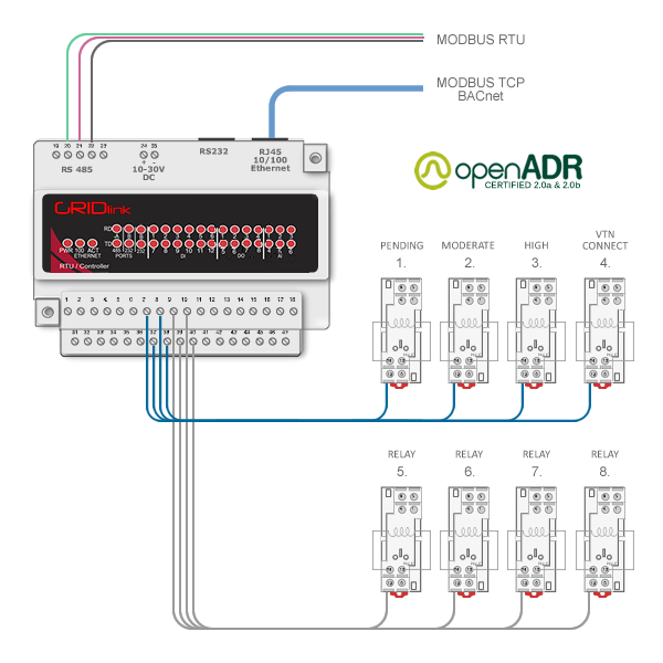
GRIDlink 135 series has 8 onboard relay outputs which will provide all the functionality described here.
GRIDlink 113 series fully executes the control logic and the virtual registers can be accessed by the BMS or a remote I/O module.
| relayConfig | Control Logic Description |
| 0 | no configuration |
| 1 | Pre-Empt (Pre-Cool) Relay 5 per ramp_start5 time in seconds |
| 2 | Gemini Dual VENs (Shared Relays) VEN1 = Relays 2 & 3 for MODERATE / HIGH signals from VTN1. Pre-Cool Relay 5 per ramp_start5 time in seconds VEN2 = Relays 2 & 3 for MODERATE / HIGH signals from VTN2. Pre-Cool Relay 5 per ramp_start5 time in seconds If overlapping Events with MODERATE & HIGH signals occur the logic will select the higher signal while in effect Single Relay Output can be configured |
| 3 | Pre-Empt / Extend Event times for Relays 5-8 based on ramp_start5-8 and ramp_end5-8 time in seconds. Create resource zones to prevent end of DR Event snapback. |
| 4 | Gemini Dual VENs VEN1 = Relays 2 & 3 for MODERATE / HIGH signals from VTN1. Pre-Cool Relay 5 per ramp_start5 time in seconds VEN2 = Relays 6 & 7 for MODERATE / HIGH signals from VTN2. Pre-Cool Relay 8 per ramp_start8 time in seconds Single Relay Output can be configured |
| 5 | Business Interruption Program (SCE) curtail on PENDING |
| 100 | Dynamic ADR – analog output based on PID loop calculation. Relays ON-OFF based on setpoint and deadband settings. |
Modbus Registers Table (Relay Logic)
| Type | Native IO Reg | Read/Write | Modbus Reg | Tag Name | Description | |
| DI-10 | 22 | R/W | 1: | 0022 | SINGLE_RELAY_OUT | << Moderate Only – High Only |
| DO-11 | 0 | R | 0: | 0001 | RELAY1 | .. Onboard Relay 1 (PENDING) |
| 1 | R | 0: | 0002 | RELAY2 | .. Onboard Relay 2 (MODERATE) | |
| 2 | R | 0: | 0003 | RELAY3 | .. Onboard Relay 1 (HIGH) | |
| 3 | R | 0: | 0004 | VTN_READ | .. VTN Connection Status not configurable | |
| 4 | R | 0: | 0005 | RELAY5 | .. Onboard Relay 5 | |
| 5 | R | 0: | 0006 | RELAY6 | .. Onboard Relay 6 | |
| 6 | R | 0: | 0007 | RELAY7 | .. Onboard Relay 7 | |
| 7 | R | 0: | 0008 | RELAY8 | .. Onboard Relay 8 | |
| 121 | R/W | 0: | 0122 | USER_TRANSF_IO | << Transfer Relay Logic to all Relays | |
| 122 | R/W | 0: | 0123 | USER_TRANSF_IO1 | << Transfer logic_relay1 to Relay 1 | |
| 122 | R/W | 0: | 0124 | USER_TRANSF_IO2 | << Transfer logic_relay2 to Relay 2 | |
| 122 | R/W | 0: | 0125 | USER_TRANSF_IO3 | << Transfer logic_relay3, 5-8 to Relay 3, 5-8 | |
| 140 | R | 0: | 0141 | logic_relay1 | .. Digital Output Relay 1 | |
| 141 | R | 0: | 0142 | logic_relay2 | .. Digital Output Relay 2 | |
| 142 | R | 0: | 0143 | logic_relay3 | .. Digital Output Relay 3 | |
| 143 | R | 0: | 0144 | logic_relay4 | .. Digital Output Relay 4 | |
| 144 | R | 0: | 0145 | logic_relay5 | .. Digital Output Relay 5 | |
| 145 | R | 0: | 0146 | logic_relay6 | .. Digital Output Relay 6 | |
| 146 | R | 0: | 0147 | logic_relay7 | .. Digital Output Relay 7 | |
| 147 | R | 0: | 0148 | logic_relay8 | .. Digital Output Relay 8 | |
| AI-0 | 101 | R/W | 3: | 0102 | relayConfig | << Define relays 2-8 response to Event (0-5) |
| 102 | R/W | 3: | 0103 | pendConfig | << Define Pend relay response to Event (0-1) | |
| LI-20 | 26 | R/W | 3: | 5053 | ramp_start1 | .. Start Event Early seconds – RELAY 1 |
| 27 | R/W | 3: | 5055 | ramp_start2 | .. Start Event Early seconds – RELAY 2 | |
| 28 | R/W | 3: | 5057 | ramp_start3 | .. Start Event Early seconds – RELAY 3 | |
| 29 | R/W | 3: | 5059 | ramp_start5 | .. Start Event Early seconds – RELAY 4 | |
| 30 | R/W | 3: | 5061 | ramp_start6 | .. Start Event Early seconds – RELAY 5 | |
| 31 | R/W | 3: | 5063 | ramp_start7 | .. Start Event Early seconds – RELAY 6 | |
| 32 | R/W | 3: | 5065 | ramp_start8 | .. Start Event Early seconds – RELAY 7 | |
| 33 | R/W | 3: | 5067 | ramp_end1 | .. Extend Event seconds – RELAY 1 | |
| 34 | R/W | 3: | 5069 | ramp_end2 | .. Extend Event seconds – RELAY 2 | |
| 35 | R/W | 3: | 5071 | ramp_end3 | .. Extend Event seconds – RELAY 3 | |
| 36 | R/W | 3: | 5073 | ramp_end5 | .. Extend Event seconds – RELAY 4 | |
| 37 | R/W | 3: | 5075 | ramp_end6 | .. Extend Event seconds – RELAY 5 | |
| 38 | R/W | 3: | 5077 | ramp_end7 | .. Extend Event seconds – RELAY 6 | |
| 39 | R/W | 3: | 5079 | ramp_end8 | .. Extend Event seconds – RELAY 7 | |
Notes:
(1) USER_TRANSF_IO when TRUE writes relay logic of logic_relay1-8 to onboard Relays 1-8 with the exception of Relay 4. USER_TRANSF_IO1-3 will default to FALSE. When USER_TRANSF_IO is FALSE relays remain in the last state and can be manually turned ON-OFF.
(2) When USER_TRANSF_IO is FALSE and USER_TRANSF_IO1 is TRUE, only logic_relay1 will be written to Relay 1. All other relays will remain in Manual.
(3) When USER_TRANSF_IO is FALSE and USER_TRANSF_IO2 is TRUE, only logic_relay1 will be written to Relay 2. All other relays will remain in Manual.
(4) When USER_TRANSF_IO is FALSE and USER_TRANSF_IO3 is TRUE, logic_relay3, 5-8 will be written to Relay 3, 5-8. All other relays will remain in Manual.