* Quick Start Guide (Gemini-ADR)
Prior to arriving at the job site..
Sign Up for GRIDview
Obtain an account to make installation easier. Sign Up..
Notify Support via email (support@gridlinktechnologies.com) that you wish to be added to a GRIDview account.
Schedule Support
If this is your first installation, it is important to contact support to schedule a time for us to be available to answer any questions that may arise during the installation.
Schedule through: support@gridlinktechnologies.com
Include a return phone number.
Test GRIDlink
It is always recommended to power up the GRIDlink and connect to the Internet on a known network like your home or office before installation. Confirm it is online with GRIDview or DO4 is illuminated. This way if GRIDlink fails to go online it is definitely the network at the job site. A few minutes spent here will save hours at the job site.
Network Planning
If you intend to use a corporate Local Area Network as the Internet connection, it is highly recommended that you contact the IT Manager before arriving at the job site. Make certain that the GRIDlink ADR will be able to operate as a DHCP client on the network by sending a letter explaining what is needed. See “Letter to IT Manager”.
IP Address (Static vs. DHCP)
GRIDlinks are shipped and configured as a DHCP client. If a Static IP Address is required, see the procedure "Change DHCP to Static IP"
GRIDview will make the installation easy
It is recommended to contact tech support and set up the GRIDview account. This will help with diagnosis and testing. Using the Subscriptions you can add the installer's phone number to receive alerts and test functionality before the VTN is set up. This way when the installer has successfully connected the GRIDlink, a text will be received confirming all is well. On installation day, bring a laptop and CAT5E cable to trouble shoot the network if necessary.
GRIDlink 6021 E Series with Onboard Cell
There are four lights on the cell modem that indicate status of the cell service and RS232. The signal LED blinking or on indicates that the antenna is connected and has signal. The WAN LED blinking or on indicates that the cellular connection is established. For the modem to have a cell connection, a SIM card will need to be installed. The SIM card is inserted on the thinner side of the cell modem next to the USB port.
Router Capabilities
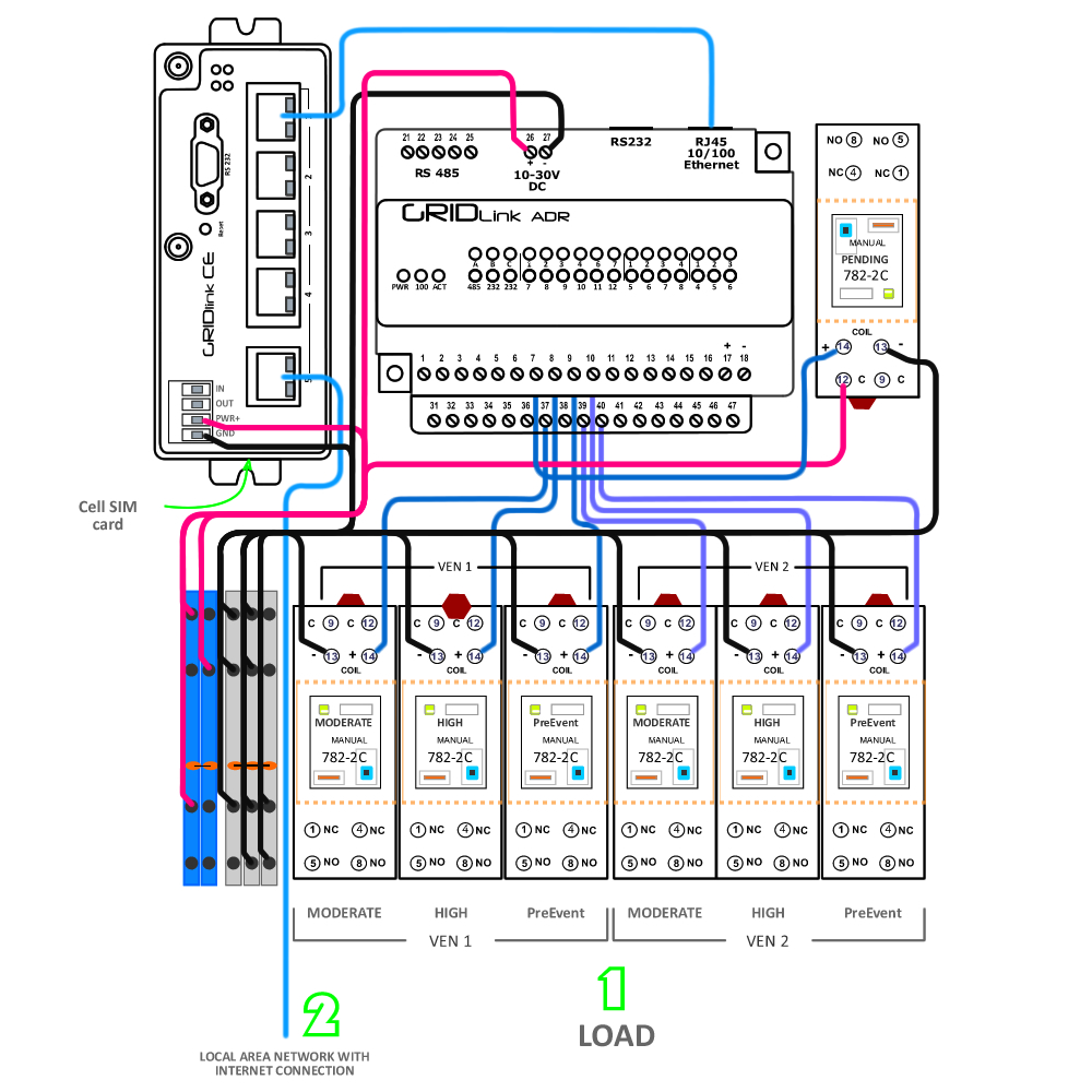
There are five 10/100 Ethernet ports on the E Series. Port 5 is the WAN port and should be plugged into the Local Area Network with a pathway to the Internet. It is the only device which needs an IP Address from the Local Area Network.
Because the E Series is also a DHCP Server, all other devices connected on Ports 1 through 4 operate as a sub network. These ports are set to receive a DHCP lease starting at 10.27.1.10 and ending at 10.27.1.50 and can be used to connect other devices like Modbus meters, HMIs or BMS . Units on the LAN ports can be configured for MAC to IP resolution in the WEB UI.
VT-mIPM 135 Series
The 135 Series has a MAC to IP resolution set in the E Series router and can be found at 10.27.27.15. If after several minutes with the power being supplied to the unit, the PWR light begins to blink, this may indicate that the 135 Series has lost its DHCP Lease. Please give the unit 5 minutes to regain connection. If the problem persists after the 5 minutes, please power cycle the entire unit. Check all connections are seated properly and power is being given to the cell modem/router.
Easy 3 Step Installation
Before drilling any enclosure penetrations, first place batteries in their desired position at the bottom of the enclosure to avoid interference. Do not attach wires.
1. Connect the Load
Gemini has 7 DPDT available relay outputs
| Relay No. | Terminal | VTN | Description | |
| 1 | Pending | 7 | Both | Beacon when either VTN is Pending |
| 2 | Moderate | 37 | 1 | Moderate Signal |
| 3 | High | 8 | 1 | High Signal |
| VTN | 38 | 1 | VTN 1 Parse Successful | |
| 5 | PreEvent | 9 | 1 | Configurable time before Event |
| 6 | Moderate | 39 | 2 | Moderate Signal |
| 7 | High | 10 | 2 | High Signal |
| 8 | PreEvent | 40 | 2 | VTN Parse Successful |
2. Connect to LAN
Connect Local Area Network to port 5 (WAN). The VENs will connect to their respective VTNs through this LAN. The E Series will ping Google 8.8.8.8 to establish the network has a valid Internet connection. Failure will initiate a fail-over to the cell connection and return once the Internet connection is re-established on the LAN. Install SIM card as shown.
3. UPS Battery Installation
Power down enclosure.
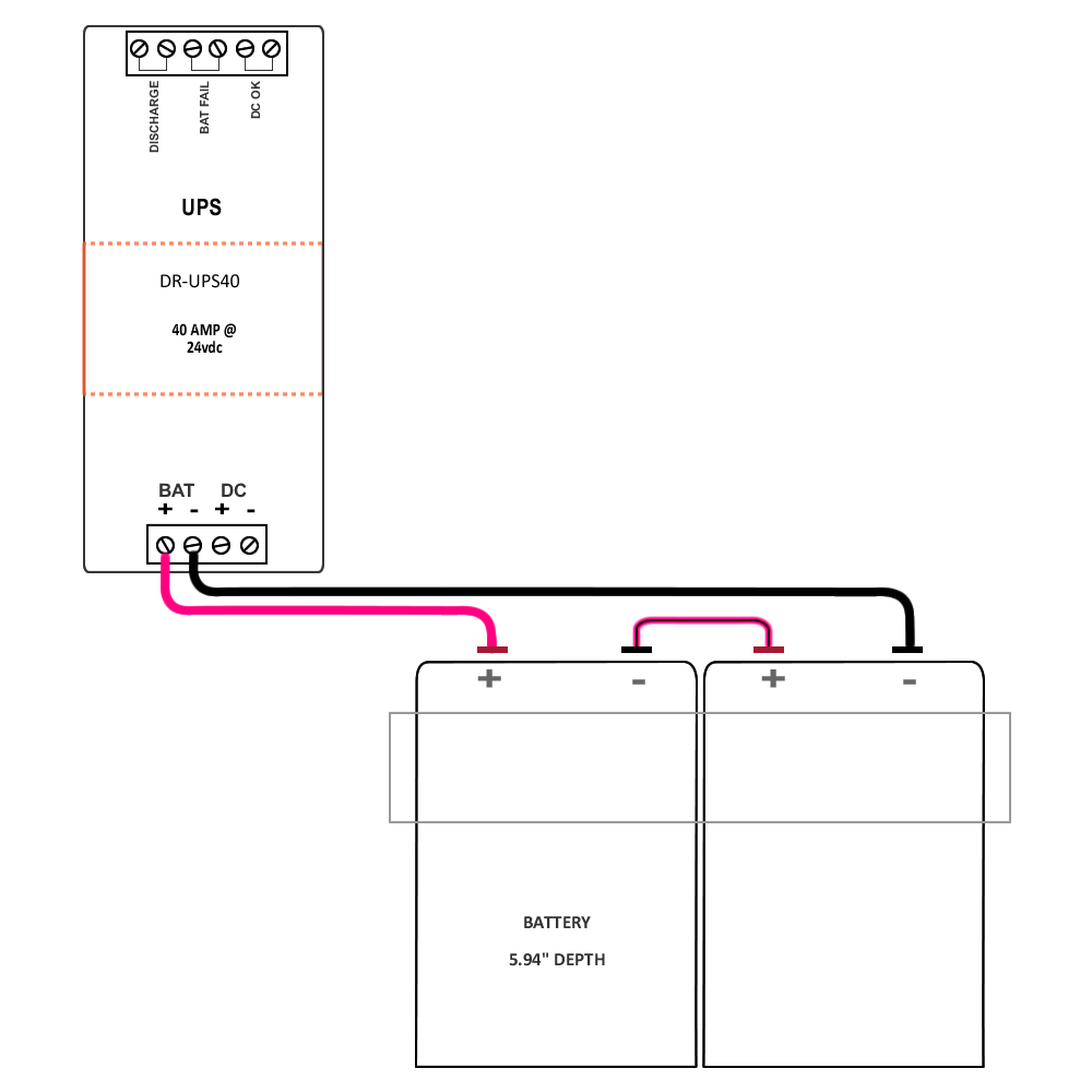
Two 12VDC batteries are shipped separately and should be installed, sitting freely on the bottom once the enclosure is mounted.
Battery terminal wires are labeled and are shipped with insulated Quick-Disconnect Terminals installed. Install the batteries and wire in series to attain the 24VDC enclosure power requirement. See diagram.
Power up – Ready to go!


