* Quick Start Guide (E2 Series-ADR)
If a cellular router is provided for the Internet, skip the Network Planning section of this document
Network Planning
If you intend to use a corporate Local Area Network as the Internet connection, it is highly recommended that you contact the IT Manager before arriving at the job site. Make certain that the GRIDlink ADR will be able to operate as a DHCP client on the network by sending a letter explaining what is needed. See “Letter to IT Manager”.
IP Address (Static vs. DHCP)
GRIDlinks are shipped and configured as a DHCP client. If a Static IP Address is required, see the procedure "Change DHCP to Static IP"
Prior to arriving at the job site..
Sign Up for GRIDview Obtain an account to make installation easier.
Schedule Support
If this is your first installation, it is important to contact support to schedule a time for us to be available to answer any questions that may arise during the installation.
Schedule through: support@gridlinktechnologies.com
Include a return phone number.
Test GRIDlink
It is always recommended to power up the GRIDlink and connect to the Internet on a known network like your home or office before installation. Confirm it is online with GRIDview or DO4 is illuminated. This way if GRIDlink fails to go online it is definitely the network at the job site. A few minutes spent here will save hours at the job site.
1. Connect load shed relays
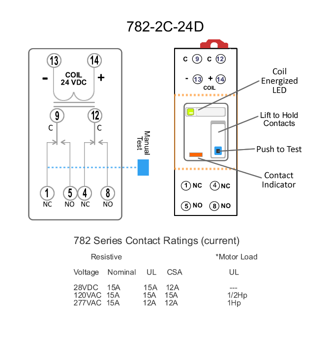
E2 Series with GRD8ID80 has 3 DPDT Relays
Pending
Moderate
High
Wire terminals
9 Common / 5 Normally Open
12 Common / 8 Normally Open
The Pending relay will be energized when the Event is announced and remain ON until the Enent is over.
A High Event will energize High & Moderate relays. A Moderate Event will energize the Moderate realy only.
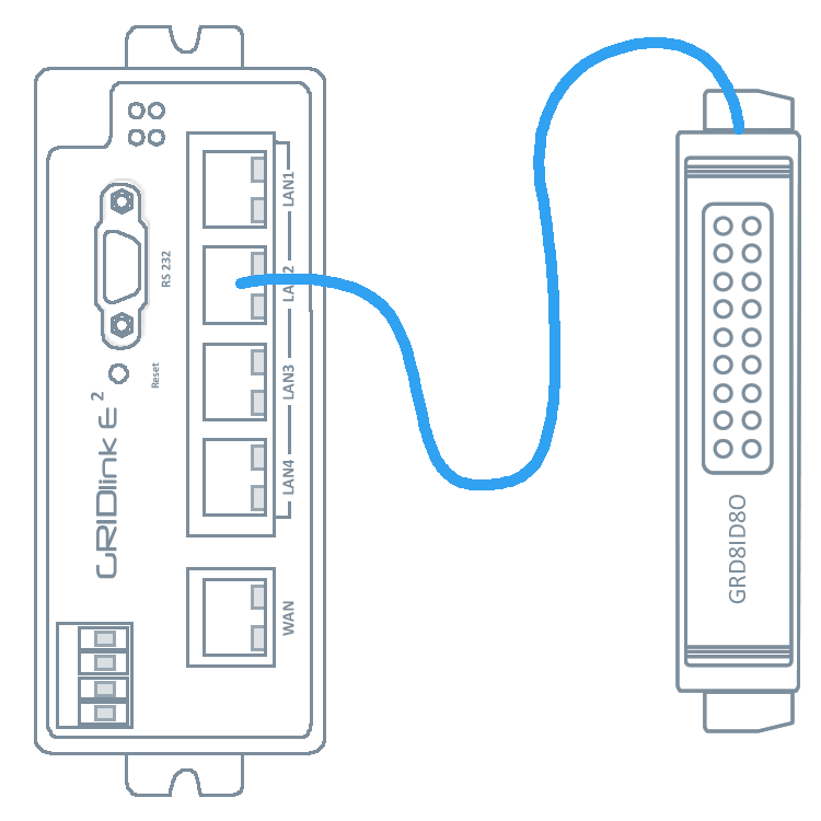
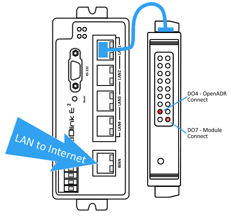
3. Insert the CAT5E cable from the LAN to the RJ45 port
Connect Local Area Network to port 5 (WAN).
Caution, connecting to any other port will prevent Internet connection
Within a minute both DO4 and DO7 LEDs will light indicating a connection to the OpenADR test server and that the Relay Module is communicating with the GRIDlink E2.
You are finished!
Router Capabilities
There are five 10/100 Ethernet ports on the E Series. Port 5 is the WAN port and should be plugged into the Local Area Network with a pathway to the Internet. It is the only device which needs an IP Address from the Local Area Network.
Because the E Series is also a DHCP Server, all other devices connected on Ports 1 through 4 operate as a sub network. These ports are set to receive a DHCP lease starting at 10.27.1.10 and ending at 10.27.1.50 and can be used to connect other devices like Modbus meters, HMIs or BMS . Units on the LAN ports can be configured for MAC to IP resolution in the WEB UI.
Connection to the Utility Server
GRIDlink is generally shipped with a test account to the Utility’s server, so this connection does not need to be configured prior to installation. It serves to confirm the connection. No test Events will be sent from this account.
When the account information for server connection is received from the Utility it can be loaded over GRIDview at any time. Contact support for any questions.


