* Quick Start Guide (113/135 ADR) Series
Network Planning
If you intend to use a corporate Local Area Network as the Internet connection, it is highly recommended that you contact the IT Manager before arriving at the job site. Make certain that the GRIDlink ADR will be able to operate as a DHCP client on the network by sending a letter explaining what is needed. See “Letter to IT Manager”.
IP Address (Static vs. DHCP)
GRIDlinks are shipped and configured as a DHCP client. If a Static IP Address is required, see the procedure "Change DHCP to Static IP"
Prior to arriving at the job site..
Sign Up for GRIDview
Obtain an account to make installation easier. Sign Up..
Notify Support via email (support@gridlinktechnologies.com) that you wish to be added to a GRIDview account.
Schedule Support
If this is your first installation, it is important to contact support to schedule a time for us to be available to answer any questions that may arise during the installation.
Schedule through: support@gridlinktechnologies.com
Include a return phone number.
Test GRIDlink
It is always recommended to power up the GRIDlink and connect to the Internet on a known network like your home or office before installation. Confirm it is online with GRIDview or DO4 is illuminated. This way if GRIDlink fails to go online it is definitely the network at the job site. A few minutes spent here will save hours at the job site.
Easy 3 Step Installation
After you have mounted your GRIDlink ADR either on a DIN rail or surface mount using the 2 mounting screw holes provided it is then a simple 3 step process.
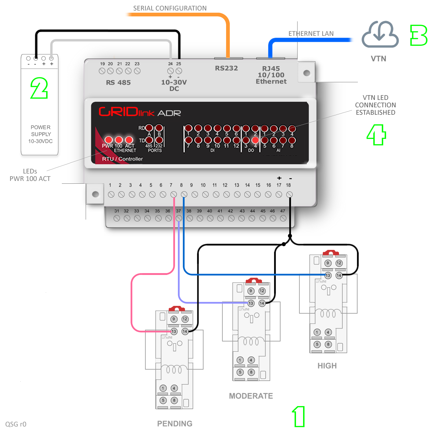
1. Connect your load shed relays.
-
- Most Utilities use the HIGH relay for load shedding. Terminals: (-) 18 (+) 8
- MODERATE was created for a second tier lesser load shed but is not always used so it is optional. Terminals: (-) 18 (+) 37
- PENDING (also optional) can be used to notify personnel that an Event is coming. The relay can be wired to a beacon for example. Terminals: (-) 18 (+) 7
You have 2 methods available to test the relay connections:
2. Connect 10-30VDC regulated power to terminals 24 & 25.
-
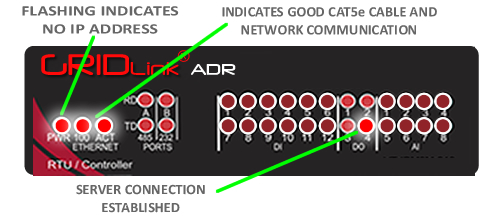
- You should see the PWR LED illuminate. If you have a GRIDlink assembled in an enclosure then this should already been wired and all that is needed is to wire the AC to the power supply.
3. Insert the CAT5E cable from the LAN to the RJ45 port on the top of the controller.
-
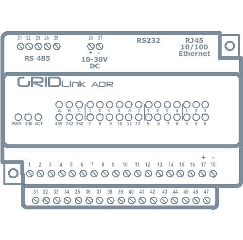
- Caution, there are 2 RJ45 ports on top of the controller. The one one the right is Ethernet. The one one the left is RS232.
- You should immediately see the Ethernet 100 and ACT LEDs illuminate. This is an indication that the cable is good,it is seated properly in the port and it is connected to a network.
- GRIDlink supports DHCP so it will obtain it’s IP address automatically from the network. After about 2 minutes, the PWR LED should be ON solid. If it is blinking then the GRIDlink was not able to obtain an IP address. If the GRIDlink has been left on for several hours without a CAT5E cable connection it probably has not been able to acquire an IP address, it may need to be power cycled.
- If the GRIDlink still does not acquire an IP address then check the trouble shooting Guide or contact the IT Manager. You will need the MAC Address which is printed on the GRIDlink module.
4. DO4 will illuminate when connected to the VTN
Within 2 or 3 minutes of acquiring an IP address from the DHCP server on the local network.
If the local network allows it, the GRIDlink will connect to the Utility’s VTN or a test site and when successful the DO4 will illuminate.
If a Text Message Subscription was set up in advance, a SMS text will be received stating that the GRIDlink is ON LINE with GRIDview.
You are finished!
Connection to the Utility Server
GRIDlink is generally shipped with a test account to the Utility’s server, so this connection does not need to be configured prior to installation. It serves to confirm the connection. No test Events will be sent from this account.
When the account information for server connection is received from the Utility it can be loaded over GRIDview at any time. Contact support for any questions.


